Laser sources are typically used in 3D depth mapping of random and pseudo-random pattern projectors. This is because laser sources are coherent enough to diffract through a diffractive optical element (DOE), unlike non-coherent sources (LED), which can’t.
The downside of highly coherent lasers is related to the inherent laser speckle effect which reduces the accuracy and sharpness of the projected pattern. This effect can be critical for high-resolution and/or high-density patterns.
OFH has developed methods to decrease speckle effect allowing for significant improvement of the projected pattern quality. The improvements allow for higher accuracy 3D-mapping systems without the use of software filtering.
The image below was taken with a long focal length camera: it shows the complex structure of the light spots made by a laser and DOE projection system. The complexity of the illuminance distribution means that the intensity of a spot may appear differently depending on the camera location.
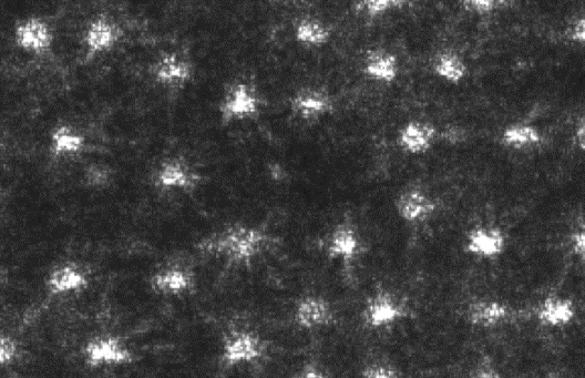
Depending on the camera location, the intensity of a spot can differ
An image of the same area with the same camera shifted a couple of millimeters will differ from this image due to speckle effect.
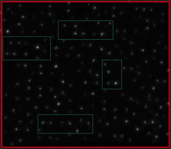
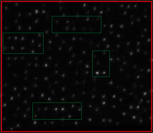
When the pattern is imaged with wide angle lenses, the image of the light spot (dot) covers just a couple of pixels. As a result, images of spots a couple of millimeters apart can differ significantly. The images below were created with a stereo-system with 250mm base, two 4mm lenses, two 5MP cameras, and a custom pattern projector. The differences in the spot intensity can be clearly seen.
Need assistance designing a custom optic or imaging lens ? Learn more about our design services here.
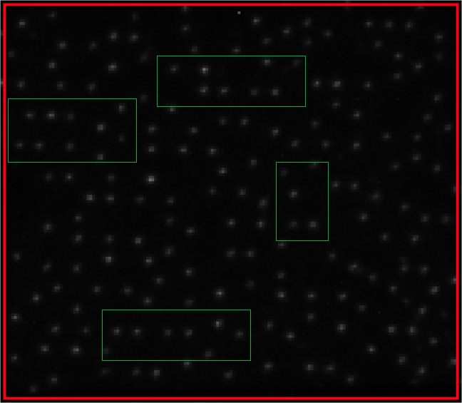
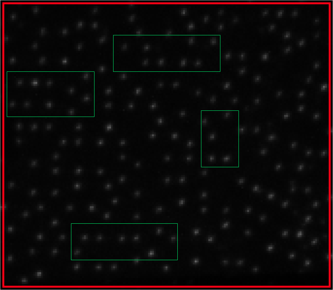
The second pair of images below were taken with the same camera set up using OFH’s speckle reduction methods. The highlighted spots in the left and right images now have more uniform illuminance.
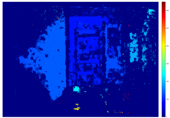
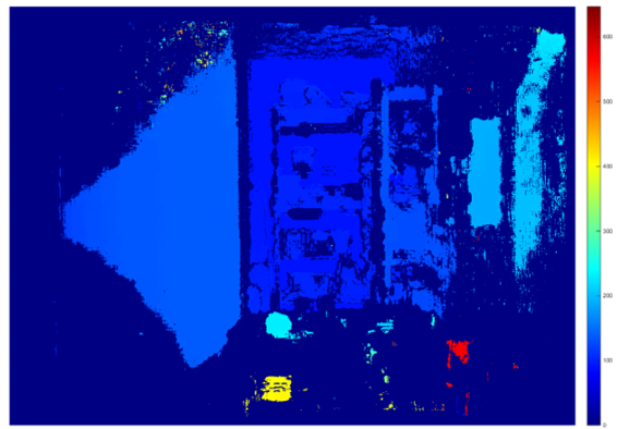
The benefits of the reduced speckle can be seen in the 3D map below. This map was created with OFH software and shows a scene in our laboratory. The image on the left uses the initial laser pattern. The image on the right was created with the same software with the additional speckle reduction method. The reduction in noise levels and higher accuracy can be easily seen.
