When doing optical simulations using a program like ZEMAX, we can choose to do our simulations using two modes: sequential and non-sequential optics. Sequential optics, as the name indicates, follows the optical path of light as it goes from one surface to the next. For example in Cooke Triplet shown in Figure 1, light travels from left to right in a predetermined sequence where light travels through each surface just once until it hits the image plane.
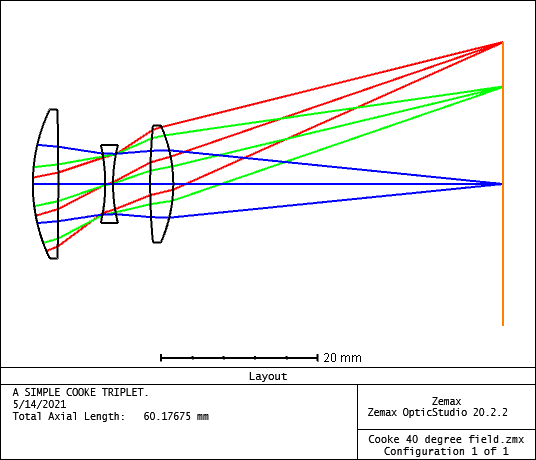
FIgure 1. Simple cooke triplet, using sequential optics. Image from ZEMAX example design
Sequential optics are the perfect choice when designing imaging lenses from photographic to microscope lenses, telescopes, and relay lenses among many other designs. Sequential optics are computationally fast and are great to define tolerances and aberrations. However, they also have some limitation in the kind of systems that we can simulate with them and that’s where non-sequential systems come into play.
When to use non-sequential optics?
Now, let’s look at the Optical layout of an ophthalmoscope illumination system we designed, shown in Figure 2. Light from a LED (on the bottom) passes a pair of condensers and the light is reflected by a folding mirror. The light is then directed by an objective lens back to the eye. This light illuminates the retina and light from the retina bounces back through the same path, light goes through an aperture in the folding mirror,and focuses on a camera sensor.
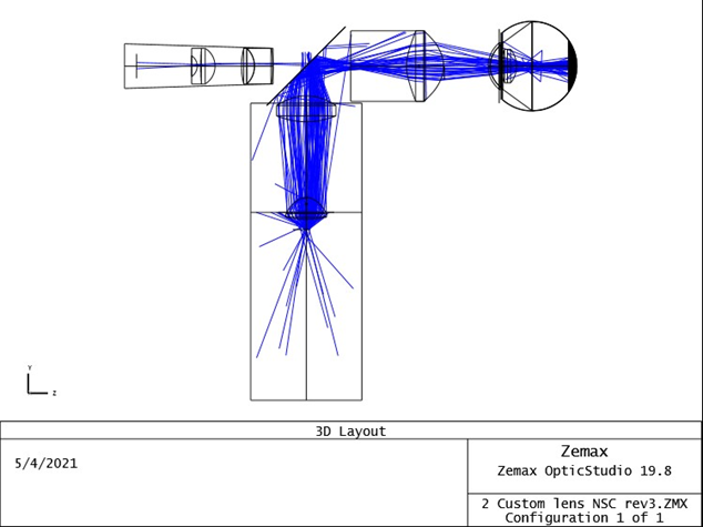
Figure 2. Optical layout of ophthalmoscope illumination for eye test
Now, to understand the need of non-sequential optics we can see in the previous example that light passes a couple of times through the eye model and the folding mirror. Also some of the optical rays that missed the folding mirror aperture will travel back to the LED condensers. So the path that each individual ray follows can be completely different from its neighbor. Such a system cannot be simulated using sequential optics; we need to use non-sequential ones.
Non-sequential optics are also needed when using optical lighting components including street lights, flashlights, commercial lighting, light pipes, beam-splitters, interferometers and/or diffraction gratings. For example, Figure 3 shows an optical layout of Cherny-Turner spectrograph. An incoherent light source is reflected by a first mirror onto a diffraction grating. The diffraction grating then reflects diffracted rays onto a second mirror before the rays reach a linear detector.
