This is our last entry on our scanning mirrors series. In this article, we will talk about the use of scanning mirrors when working with welding environments. As you can imagine, not only do the optical requirements differ when compared to those of a scanning microscope, but the mechanical requirements will change considerably as well due to the harsher welding station environment.
Laser Welding
Laser welding is a process in which metal pieces are joined together with a laser. The laser provides a focused heat source at the joint between two elements. This process is quite common in industrial settings such as the auto industry. Laser welding is a high-power process that tends to be more efficient than other types of like arc-welding.
A very common welding technique used when working with lasers is called keyhole welding. In this process-as defined by the American Welding Society-”is a technique in which a concentrated heat source penetrates partially or completely through a workpiece, forming a hole (keyhole) at the leading edge of the weld pool. As the heat source progresses, the molten metal fills in behind the hole to form the weld bead.” This process requires high powered lasers above 105W/mm2.
One of the great advantages of laser welding is that it is possible to control the welding temperature. This provides a great flexibility with the materials that can be used for welding. For example, it is possible to use laser welding to work with plastics, aluminum, glass, copper, and steel.
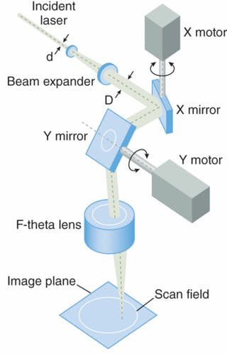
As you can imagine one of the main challenges when working with scanning mirrors is to create a reflective surface strong enough to withstand the high power needed for this application. One possible solution is the use of silicon carbide (SiC) mirrors: they provide high stiffness and high thermal conductivity when compared with traditional glass or silicon mirrors. When using SiC mirrors, it is possible to increase the scan rate and power output.

Figure 1. Scanning mirror based on Galvanometric mirrors. Image from Laser Focus World
Another interesting option for scanning mirrors is using deformable mirrors. This technique allows the user to change the focal point of the focused beam in the z-direction. The same effect can be achieved using a similar setup as the one used in Optical Coherence Tomography.
It is sometimes required that the laser fill a gap when the materials to be welded are not in perfect contact. This is called a “wobble pattern”; the pattern can have different shapes, as shown in Figure 2. Some of them are basic zig-zag lines or connected circles, but they can be more complex, such as a figure ‘8’. One of the advantages of a wobble pattern is that it is possible to use a smaller spot size, create a more consistent weld, and it allows better control the welding itself.
Figure 2. Different wobble patterns for industrial welding. Image from pmdi.com
Conclusions
As we have seen in the last four articles, scanning mirror technology is a field that is still in development with a wide set of applications. I hope you have enjoyed these brief introductions and let us know if you would like us to talk about a specific topic of application that you might have.

