This week, we will continue our discussion of fast steering mirrors. If you missed our last article, go ahead and read about steering mirrors for laser marking. Here, we will discuss the design requirements for steering mirrors in Optical Coherence Tomography (OCT). If you are not familiar with scanning microscopy (the basis of OCT), please read our article about Scanning and Fluorescent Microscope Design Steps.
Optical Coherence Microscopy
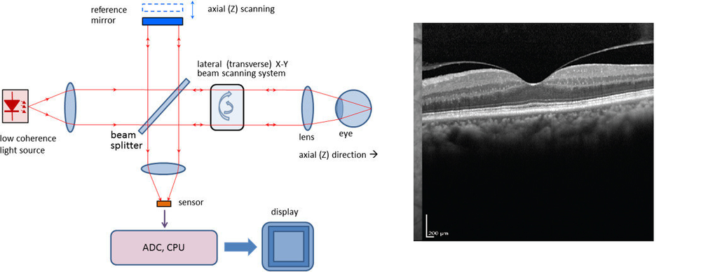
OCT is a common imaging technique that uses low-coherence light to create high resolution images (in the micrometer range). It uses an infrared light source allowing it to penetrate around 2-3 mm in highly dispersive media, such as organic tissue. For this reason, OCT is commonly used in the medical field, especially in ophthalmology where OCT allows for extremely useful mapping of the retina. Figure 1a shows a basic OCT microscope layout, and 1b shows a retina scan done by OCT.
Figure 1. a) Typical Time-domain OCT setup with a moving reference mirror (image from BioMedical Engineering OnLine 13(1):52.) b) OCT of patient retina (image from Jessica G. Lee, MD and Richard B. Rosen, MD).
In the setup shown in Figure 1, there are two important components that we are interested in today (we may talk about the light sources on a different occasion): the reference mirror with z-scanning capabilities and the lateral x-y scanning mirror. The reference mirror allow us to change the depth at which we are probing our target. By changing the z-position of the reference mirror, we can change the beam’s focal point and read at different tissue depths. On the other, the x-y scanning mirror sweeps the surface.
Steering Mirror Design Issues
We will assume that our steering mirror is mounted in a flexible support system that can be controlled to direct a laser beam to a desired position. The range of motion is an important consideration. Flexible support systems usually have a smaller range than what can be achieved using rotary bearings. With an OCT system, it is usually desired to have a range of motion of plus or minus 5-degrees in each axis.
There are usually many different kinds of actuators to control the supports: coils and piezoelectrics (PZT). Coils consist of a wire coil and a permanent magnet. By modulating the amplitude, frequency, and direction of the current flowing through the coil, it’s possible to either push or pull the mount. PZTs typically consist of laminated stacks of piezoelectric material. By applying a modulated voltage signal, we can produce small increments in position.
An optomechanical engineer is faced with the challenge of developing a mirror design that compromises neither the mechanical requirements nor the optical requirements of a given FSM application. The optical requirements are generally expressed in terms of aperture size and wavefront error. In terms of aperture, scanning mirrors for OCT usually have a surface area of a couple of squared-millimeters. Another important requirement of scanning mirrors is their scanning frequency, which is usually in the couple of hundreds of Hertz for this specific application
Figure 2 shows a proposed MEMS-based scanning mirror by Christophe Gorecki et al. This specific design has a dual-axis scanning mirror with a 1 mm diameter (with a 9 squared-millimeter footprint), a resonant frequency of 150 Hz.
Figure 2. MEMS-based 2-axis scanning mirror for OCT. Image from Christophe Gorecki et al.

