There are two primary methods of image formation in lens design.
Perspective projection (F-Tan Theta lenses also called Rectilinear or Orthoscopic).
Equidistant projection (F-Theta lenses also called Equiangular)
The Perspective projection method is most often used during the design of lenses with field of view in the 40-60 degree range. This formation method maintains straight lines in images while stretching space. For some photography types such as satellite imaging, this stretching is acceptable even at wide angles. For many applications however, it is not acceptable. The photo on the right above shows a 130 degree image with distortions.
Equidistant projection is used in wide-angle lenses like a fisheye lens. It bends straight lines but can provide more than 180 degrees of lens FOV (left photo). Moreover, this projection saves angles. This is useful in astronomy photography and many applications on earth.
There are 3 less common methods of image formation or projection these are:
Stereographic
Equisolid
Orthographic projections
Need assistance designing a custom optic or imaging lens ? Learn more about our lens design services here.
The key criteria used to evaluate which methods are best include:
Image format at given field of view depending on image construction equation
Space distortion
Object distortion
Light distribution on image
Theoretical and achievable lens field of view
Image format at given field of view depending on image construction equation
1.1 Types of projections and image formation equation
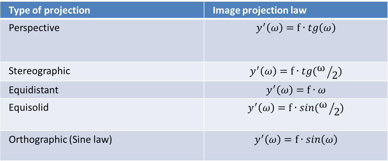
Table 1.1 Image height depends on projection law
?- angle of object FOV
y’ – image height
f – focal length
Next table shows how image size depends on type of projection for given angular FOV
1.2 Image size calculation of different types of projection for 120° FOV
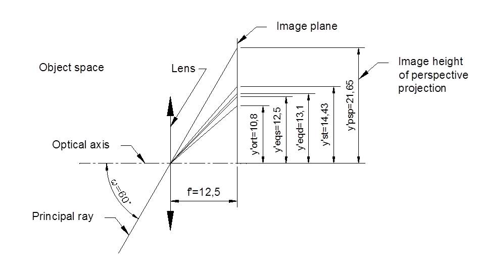
Fig 1.2 Simplified tracing of principal ray for different projections.
Focal length 12.5 mm was previously calculated based on perspective projection according with full frame diagonal format y’=21.635 as f′=y^′/tan(ω)
Then calculated focal length f’ =12.5 mm was used for all other types of projections for image height calculations.
The lens is drawn by coinciding principal planes
Different projections give different image height for given angular FOV (see below for details)
1.3 Corresponding standard sensor formats with image height calculated for given angular FOV and equal 12.5 mm Focal Length.
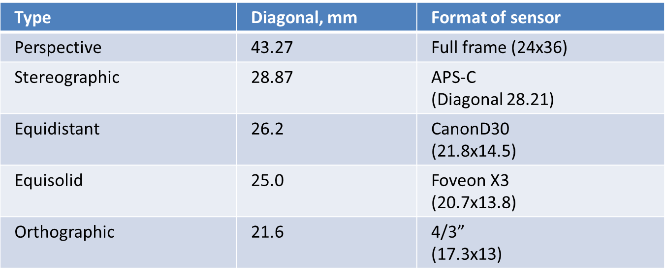
Table 1.2 Corresponding standard sensor formats with image height calculated for given angular FOV and equal 12.5 mm Focal Length.
2. Space distortion
2.1 Definition
Space distortion is defined as the ratio of paraxial value of areas forming by small solid angle at image plane for given angle ω of FOV to the area forming by equal value of solid angle at center FOV (ω=0).
Derivation of values of Space distortion was implemented in [1]
Plots of space distortion depending on the type of projection are shown below.
2.2 Relative change of area value with angle of view of perspective projection

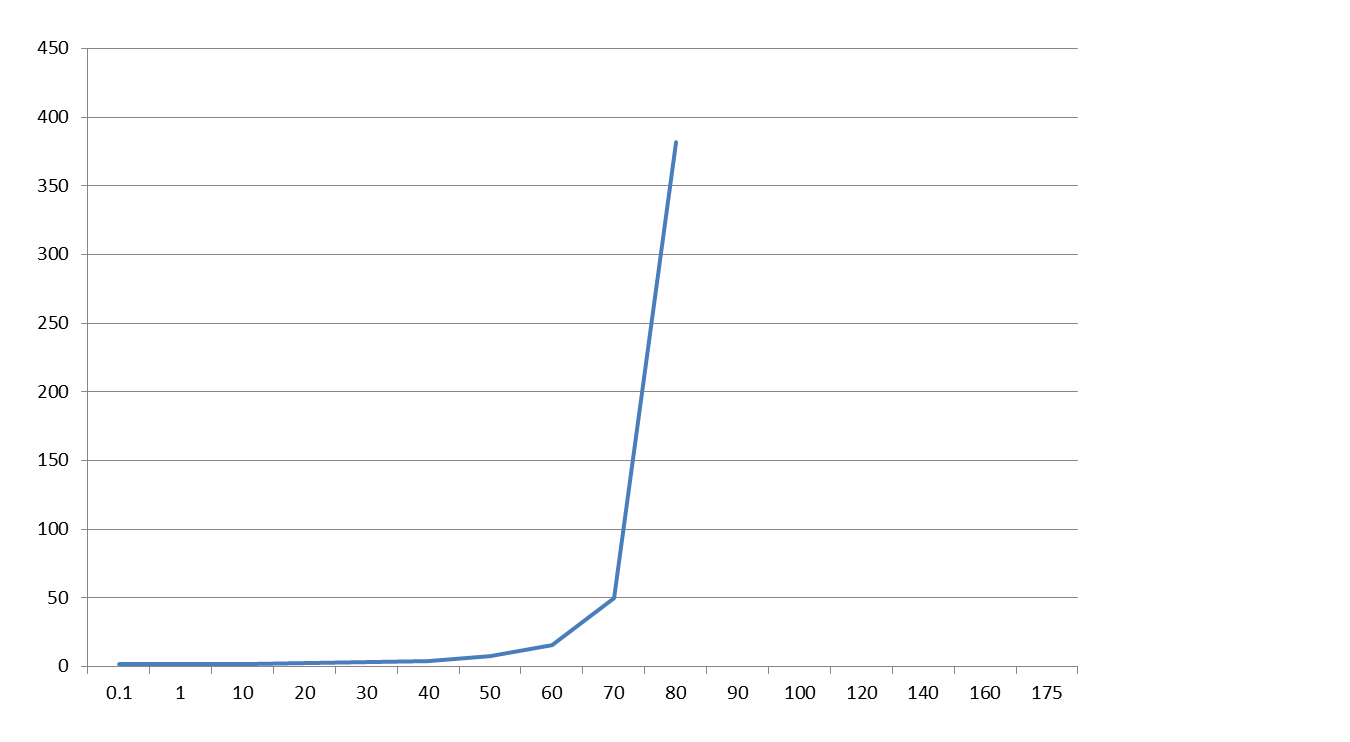
There is essential stretching space for Perspective projection after 140 deg.
2.3 Relative change of area value with angle of view of stereographic projection

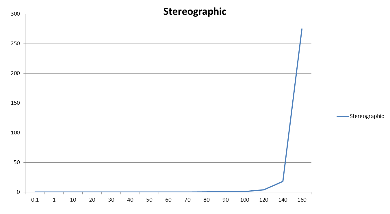
There is small stretching space for Stereographic projection up to 280 deg.
2.4 Relative change of area value with angle of view of equidistant projection

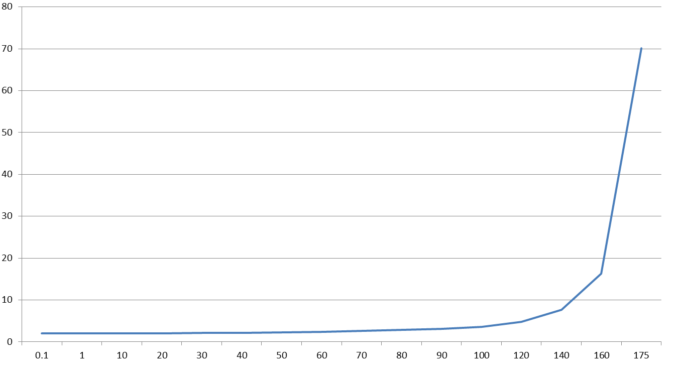
There is small stretching space for Equidistant projection after 300 deg.
2.5 Relative change of square of area with angle of view for Equisolid projection

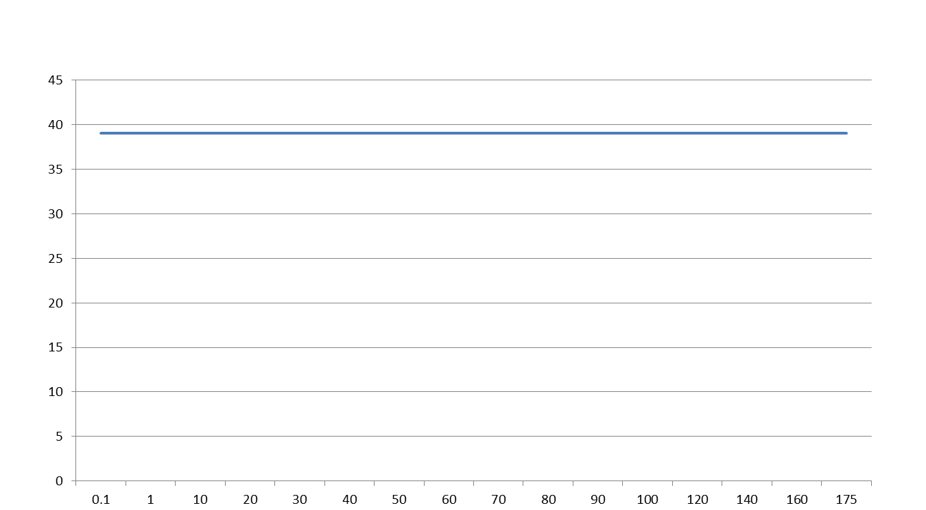
There is even space imagination for Equisolid projection.
2.6 Relative change of area value with angle of view of orthographic projection

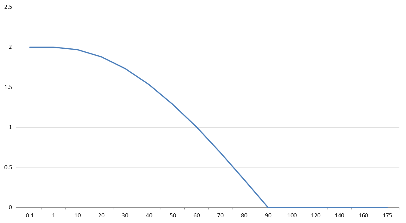
There is compression space for Orthographic projection.
2.7 Summary
– There is image stretching for Perspective, Stereographic and Equidistant projections.
– Distortion of Perspective projection limits FOV to 120-140 deg.
– Stereographic projections can provide maximal angular FOV 210-250 deg.
– Equidistant projections can provide maximal angular FOV 300-350 deg.
-There is compression space for Orthographic projection.
– Orthographic projection has 180 deg. limit of angular FOV.
– There is no space distortion for Equisolid projection.
– Equisolid projection can provide maximal angular FOV up to 360 deg.
3. Object distortion
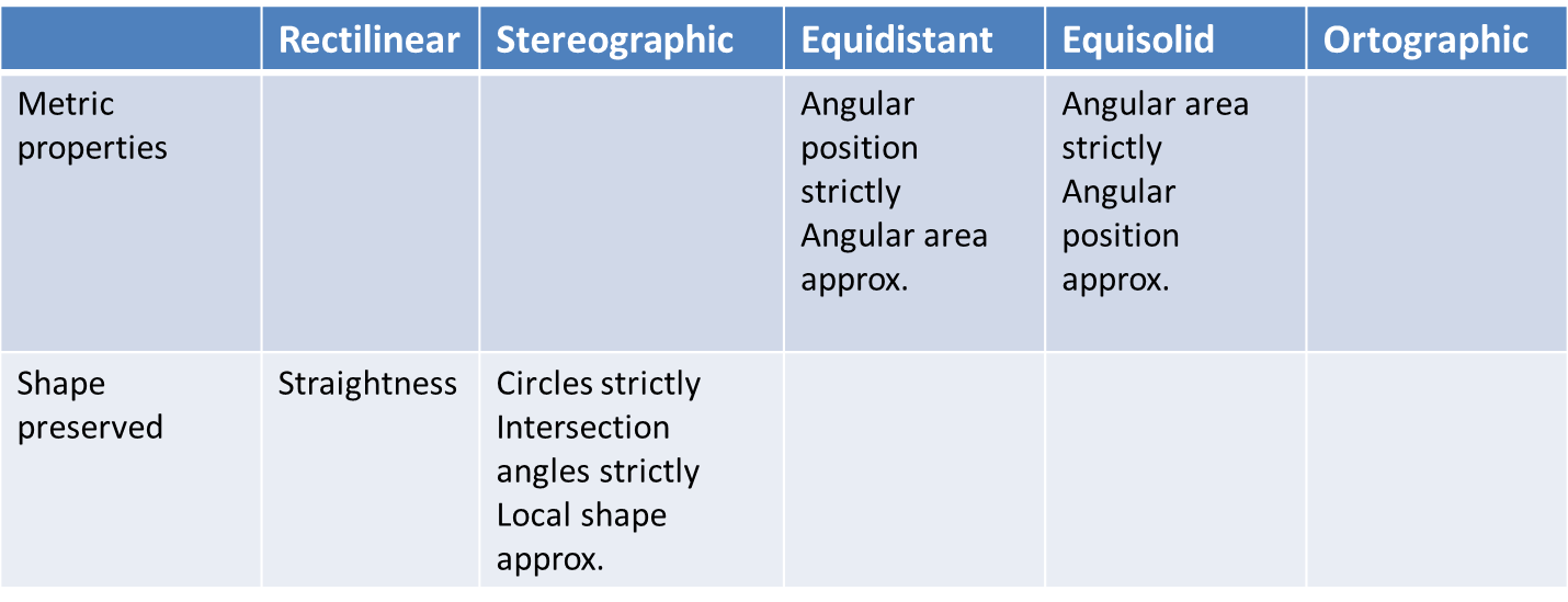
Perspective, Equidistant, Equisolid and Orthographic projections give deformation of shape of small objects through the field of view.
Only stereographic projection saves shape of small objects.
Stereographic projection preserves circles.
Stereographic projection is conformal –preserves angles of intersects of two curves
4. Distribution of illumination
4.1 Light distribution in perspective projection
Maximal field of view is limited by intensity drop-off at edge of image.
A well known formula for perspective projection describes decreasing light distribution from center to edge is

It can be used for other projections if consider changing size of square in plane of image.

Note: this equation is true if ω is the same for object space as for image space. Image illumination can be different if the ω is different for image space, a common occurence in real optical systems. This topic requires additional explanation
4.2 Distribution of illumination for different projections
Ratio of areas for Orthographic projection

Ratio of areas for Equisolid projection

For Equidistant

For Stereographic

– Orthographic projection has perfectly even image illumination.
– Equidistant has a very slow intensity decreasing.
– Equidistant, stereographic, and equi-solid provide very wide FOV because of slow intensity drop.
5. Maximal theoretical and feasible FOV

Maximal theoretical FOV based on projection equation, acceptable space distortion, and decreasing of image illumination depends on FOV
Specific properties of particular projections
6. Examples of lens design with different image projections
Below we present examples of lenses for each projection. The lenses with close parameters for each projection were found and then additionally optimized by Zemax to match the image formation equation for each projection.
Angular FOV is 120 deg. for all samples
6.1 Example of lens provided perspective projection
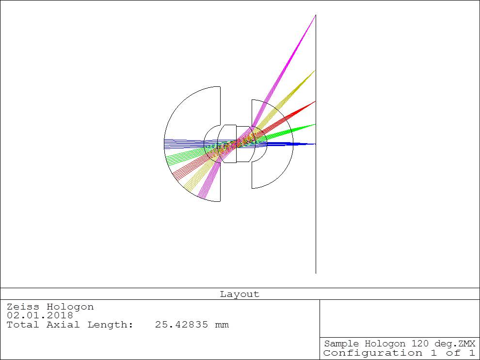
Lens layout with perspective (ortoscopic) projection
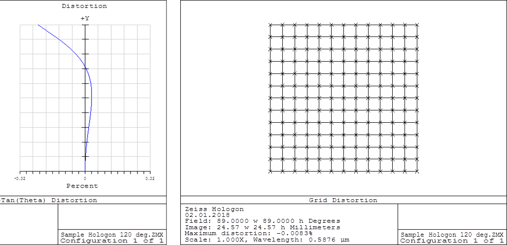
Lens distortion with perspective projection
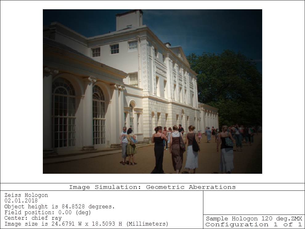
Lens image simulation with perspective projection
6.2 Example of lens with stereographic projection
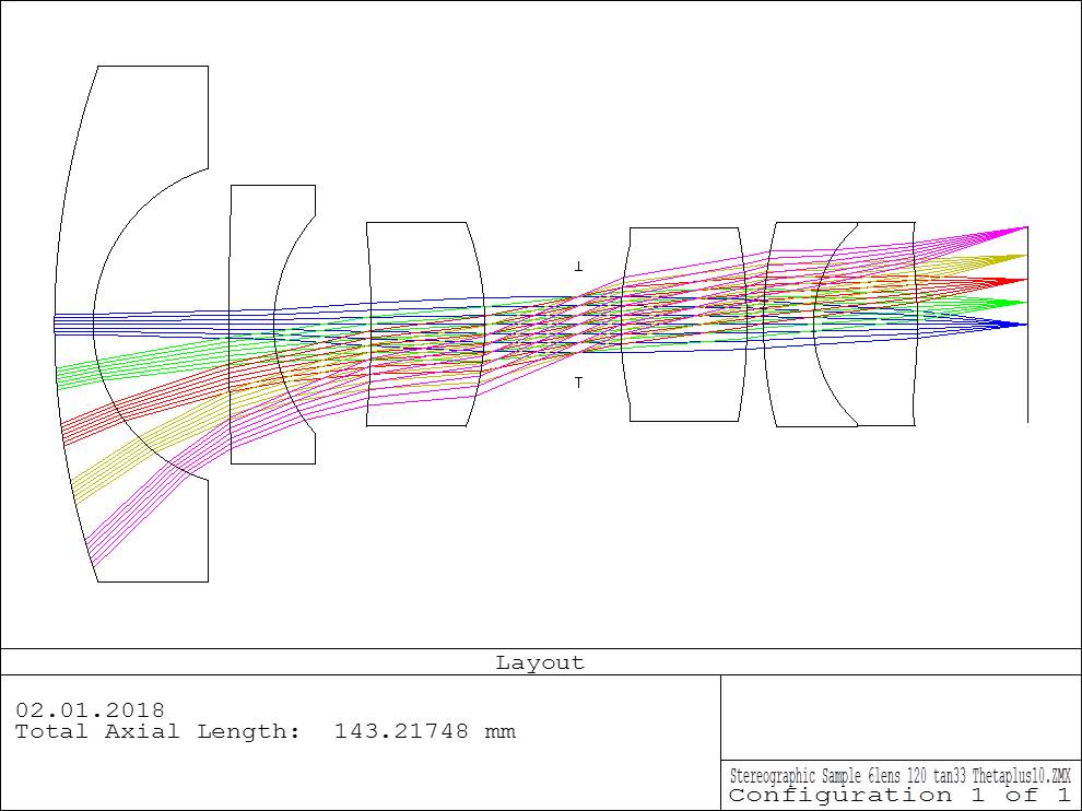
Lens layout with stereographic projection
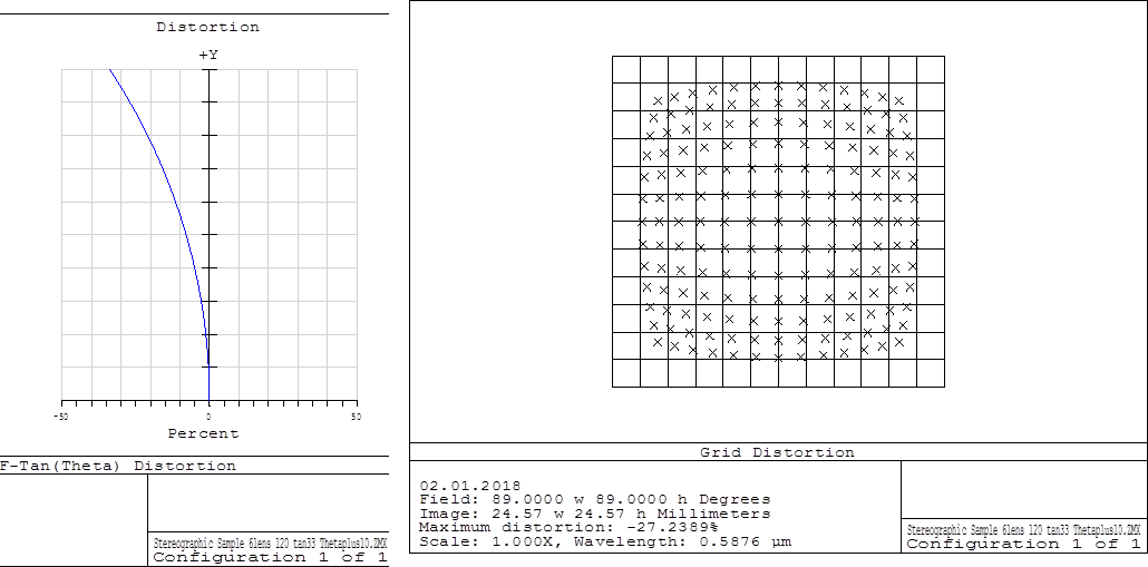
Lens distortion with stereographic projection
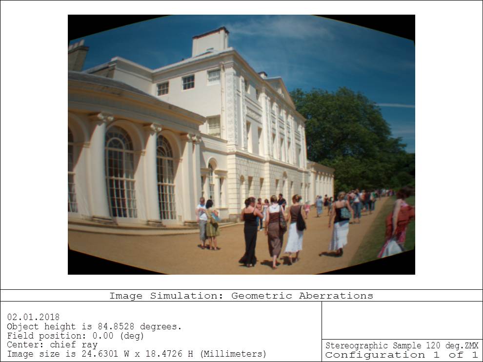
Lens image simulation with stereographic projection
6.3 Example of lens with equidistant projection
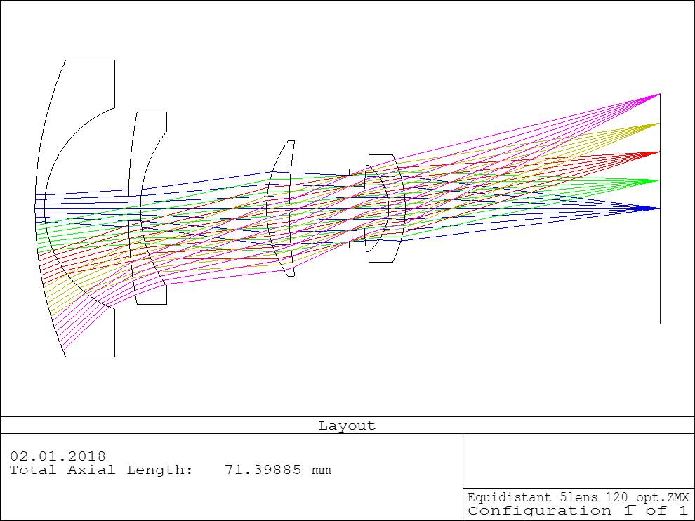
Lens layout with equidistant projection
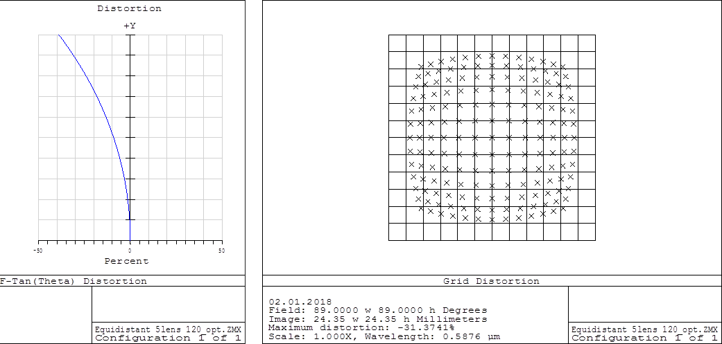
Lens distortion with equidistant projection
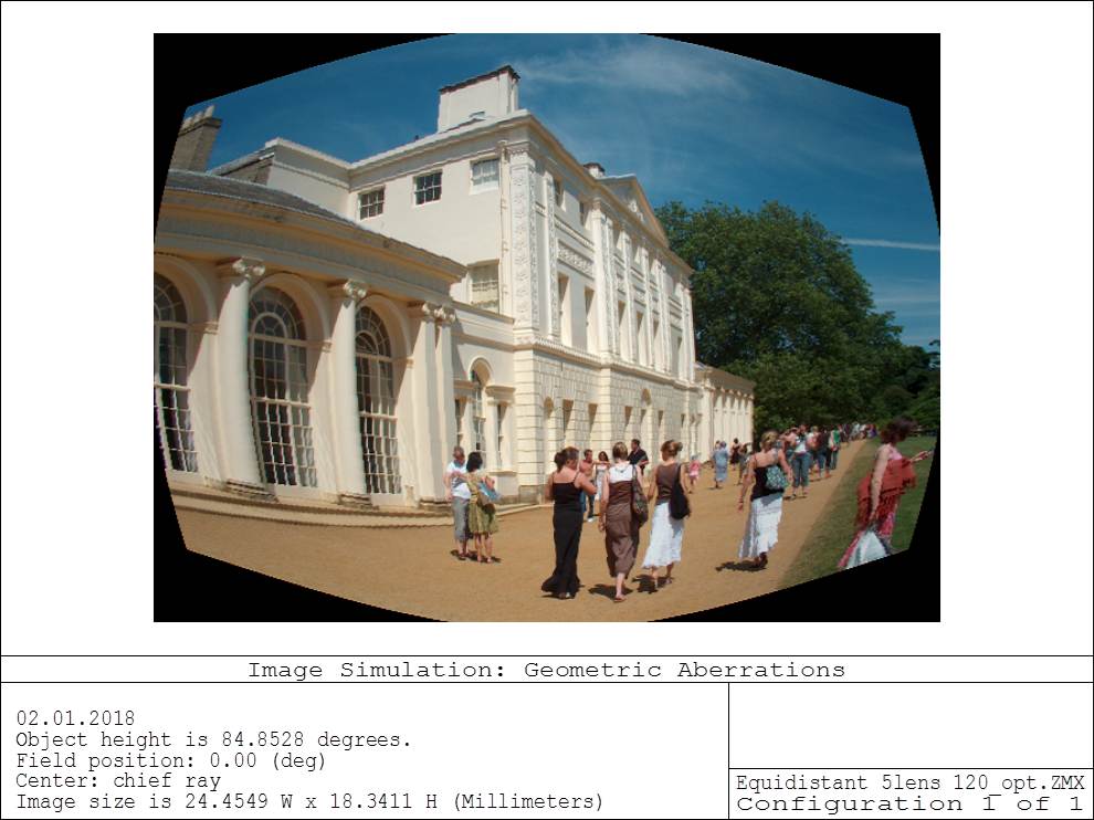
Lens image simulation with equidistant projection
6.4 Example of lens with equisolid projection
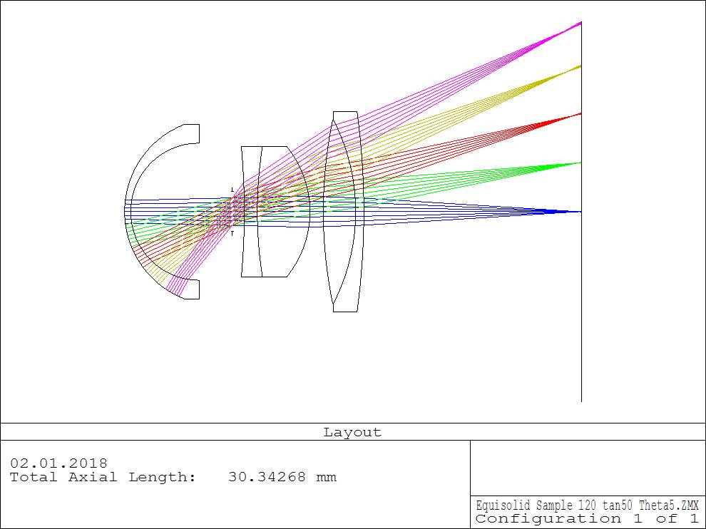
Lens layout with equisolid projection
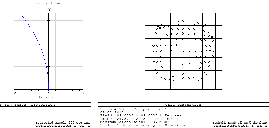
Lens distortion with equisolid projection
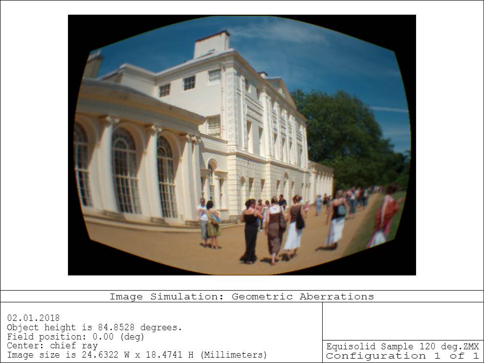
Lens image simulation with equisolid projection
6.5 Example of lens with orthographic projection
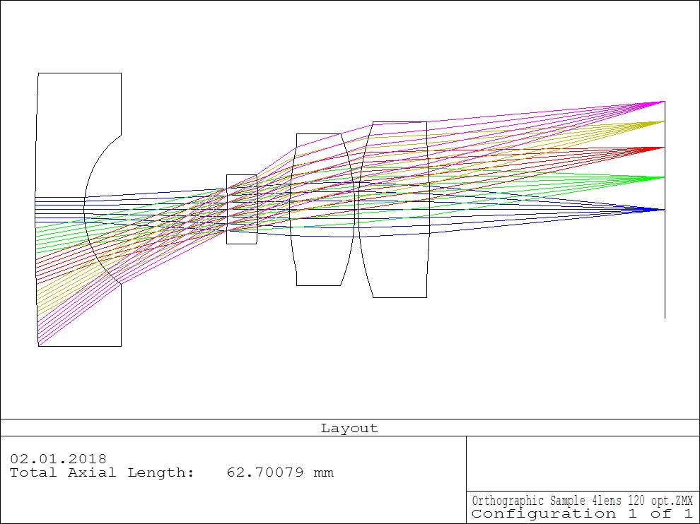
Lens layout with orthographic projection
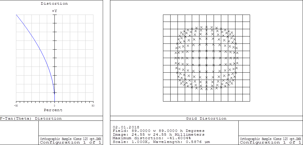
Lens distortion with orthographic projection
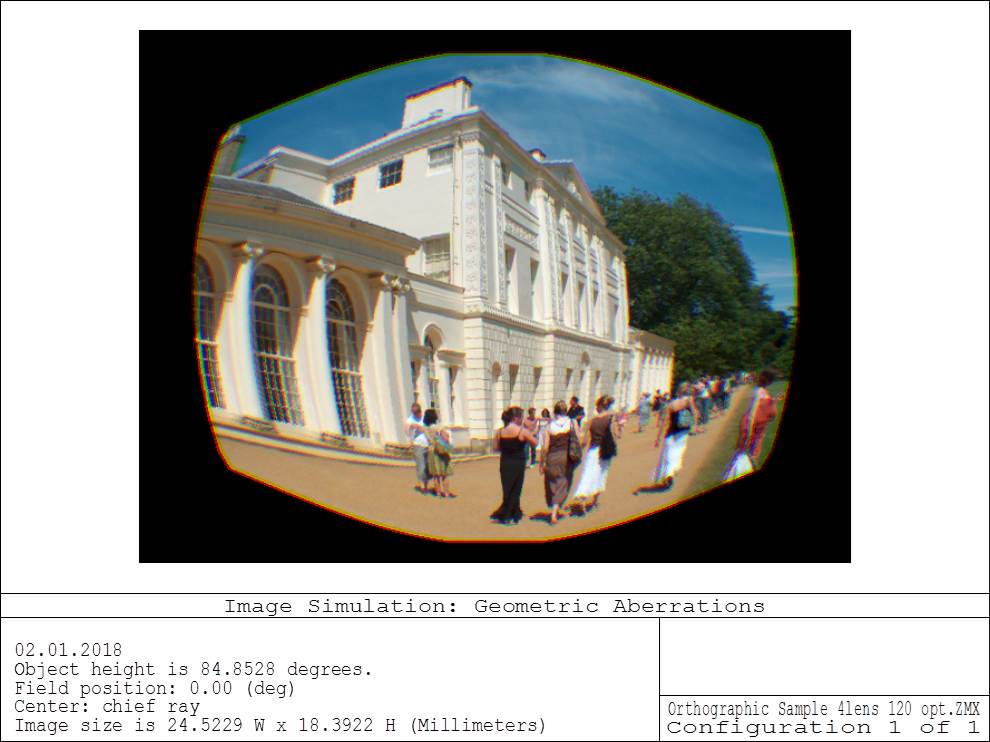
Lens image simulation with orthographic projection
7. Comparison of Image height and distortion
(F-TanTheta in Zemax) for all types of projections

This table shows value of image height and perspective distortion (referring to perspective projection) of different types of projections
8. Conclusion
All image formation or projection types can be useful. Which one depends on the application
Perspective projection is useful to preserve straight lines in an image. The maximal field of view should however be less than 140 degrees. This is widely used in photography lenses and aero photo lenses
Stereographic projection is useful if preserving the shape of small object on image plane is required. FOV can be more than 180 deg. This is widely used in machine vision systems.
Equidistant projection is useful if preserving angular sizes of object on image plane is required. FOV can be more than 180 deg. This is widely used in fish eye lenses and astronomical cameras.
Equisolid projection is useful if preserving constant ration of solid angles in object and image spaces is required. FOV can be more than 180 deg. This is used in scientific photography.
Orthographic projection is useful if evenness of illumination through the entire image plane is required. FOV can be up to 180 degrees. This is used in cheap cameras and door eye viewers.
9. Wide-Angle Lens Projections FAQ
What are the different types of projections used in wide-angle lenses?
Wide-angle lenses utilize various projections like Perspective, Equidistant, Stereographic, Equisolid, and Orthographic. Each has unique characteristics suitable for different applications, ranging from photography to scientific imaging.
How does the Perspective projection affect images in wide-angle lenses?
Perspective projection, often used in lenses with a 40-60 degree field of view, maintains straight lines in images but can cause space stretching. It’s typically utilized in photography and aero photo lenses where this distortion is acceptable.
What are the advantages of Equidistant and Stereographic projections in wide-angle lenses?
Equidistant projection, common in fisheye lenses and astronomical cameras, preserves angular sizes on the image plane and can offer over 180 degrees of field of view. Stereographic projection, used in machine vision systems, maintains the shape of small objects and can also exceed 180 degrees in field of view.
10. References of theoretical materials
1. Field of View – Rectilinear and Fishye Lenses
http://www.bobatkins.com/photography/technical/field_of_view.html
2. Margaret M. Fleck. Perspective Projection: The Wrong Imaging Model. 1995, Technical report 95-01
http://mfleck.cs.illinois.edu/my-papers/stereographic-TR.pdf
3. Models for the various classical lens projections
http://michel.thoby.free.fr/Fisheye_history_short/Projections/Models_of_classical_projections.html
4. About the various projections of the photographic objective lenses
http://michel.thoby.free.fr/Fisheye_history_short/Projections/Various_lens_projection.html
11. References of lens design
1. U.S.Patent 3661447
2. JP #: 04-267,212
3. Imaging lens and imaging device US 20090009888 A1
4. Wide-Angle Objective. Zeiss #1058 page #0550.
5. JP Patent 4238312
Exploring the World of Fisheye Lenses: Dive into the fascinating realm of fisheye lens design. Learn about the unique challenges and creative possibilities these wide-angle lenses offer.
Transform Your Photography with Lens Attachments: Discover how wide-angle and telephoto lens attachments can revolutionize your photographic experience, offering new perspectives and capabilities.
